


Polycarbonate Warping in 3D Printing
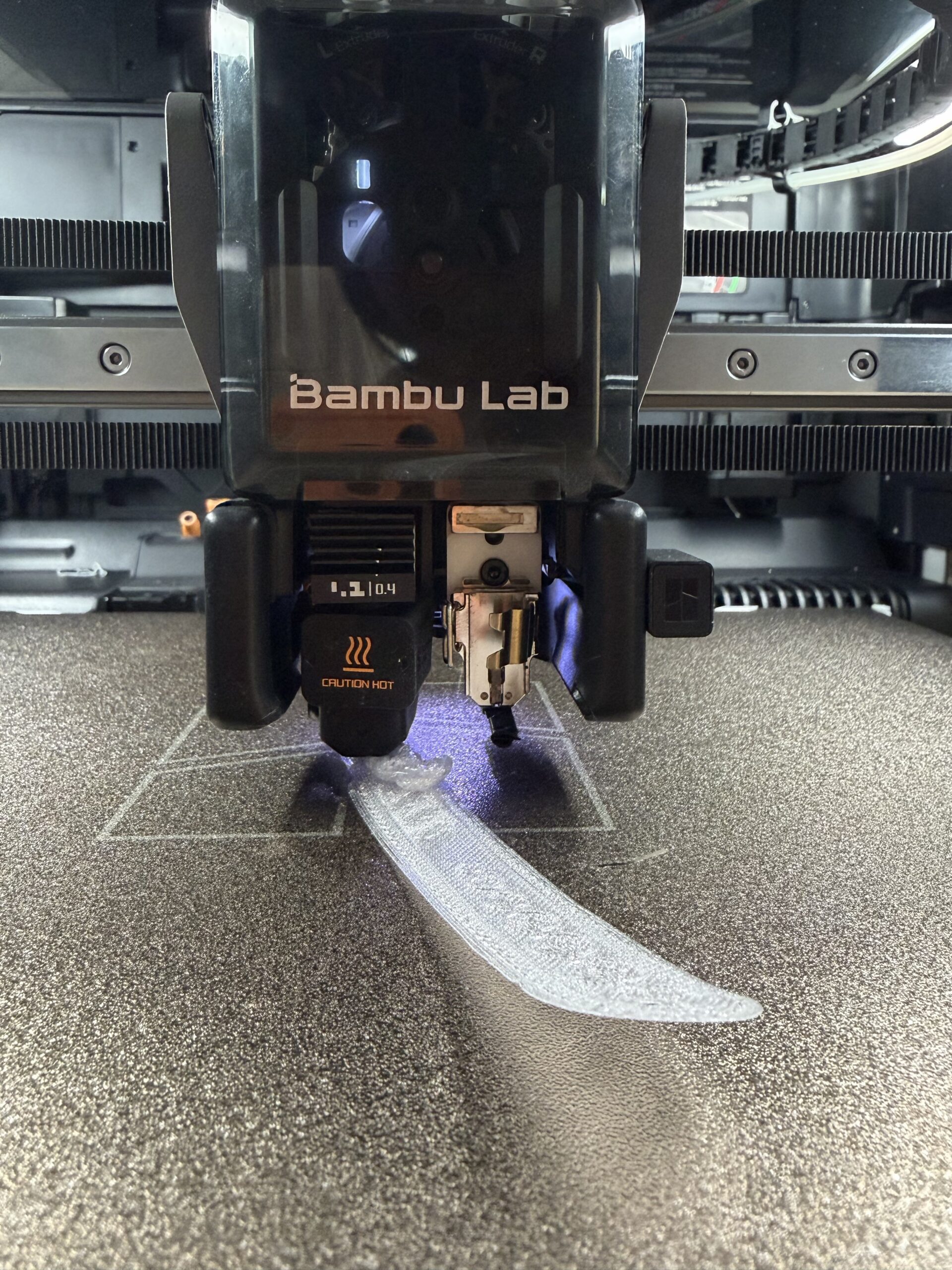
3D printing polycarbonate (PC) is known to be challenging due to its high thermal properties and significant shrinkage during cooling. This phenomenon frequently causes warping (parts lifting off the build plate), especially on standard build plates. Yet PC offers exceptional mechanical and thermal performance, making it a material of choice for demanding technical applications. The question, then, isn’t whether to replace PC, but how to secure its printing.
Why Conventional Adhesives Fall Short
In most production environments, PC adhesion is improved using external solutions: specialized high-temperature glues, adhesive sprays, technical lacquers…
However, these methods come with several major drawbacks.
Residue and Cumbersome Cleaning
Print surfaces require regular cleaning, which is often lengthy and incomplete, potentially affecting production repeatability.
Risks for Sensitive Applications
In medical or research sectors, the use of solvents or chemical agents can compromise biocompatibility requirements.
Performance Variability
The effectiveness of adhesives depends heavily on environmental conditions and operator protocol, introducing significant variability.
Using an ABS Raft to Improve PC Adhesion
A proven alternative in industrial settings consists of printing the polycarbonate part on an
ABS raft, either via a dual-extrusion setup if your printer has a dual toolhead, or by switching filaments between the raft and the part — through a multi-material system, or manually by swapping the filament during a pause.
Why the ABS Raft Works
PC and ABS exhibit good inter-polymer affinity, which is widely exploited in PC/ABS composite materials used in industry.
During printing:
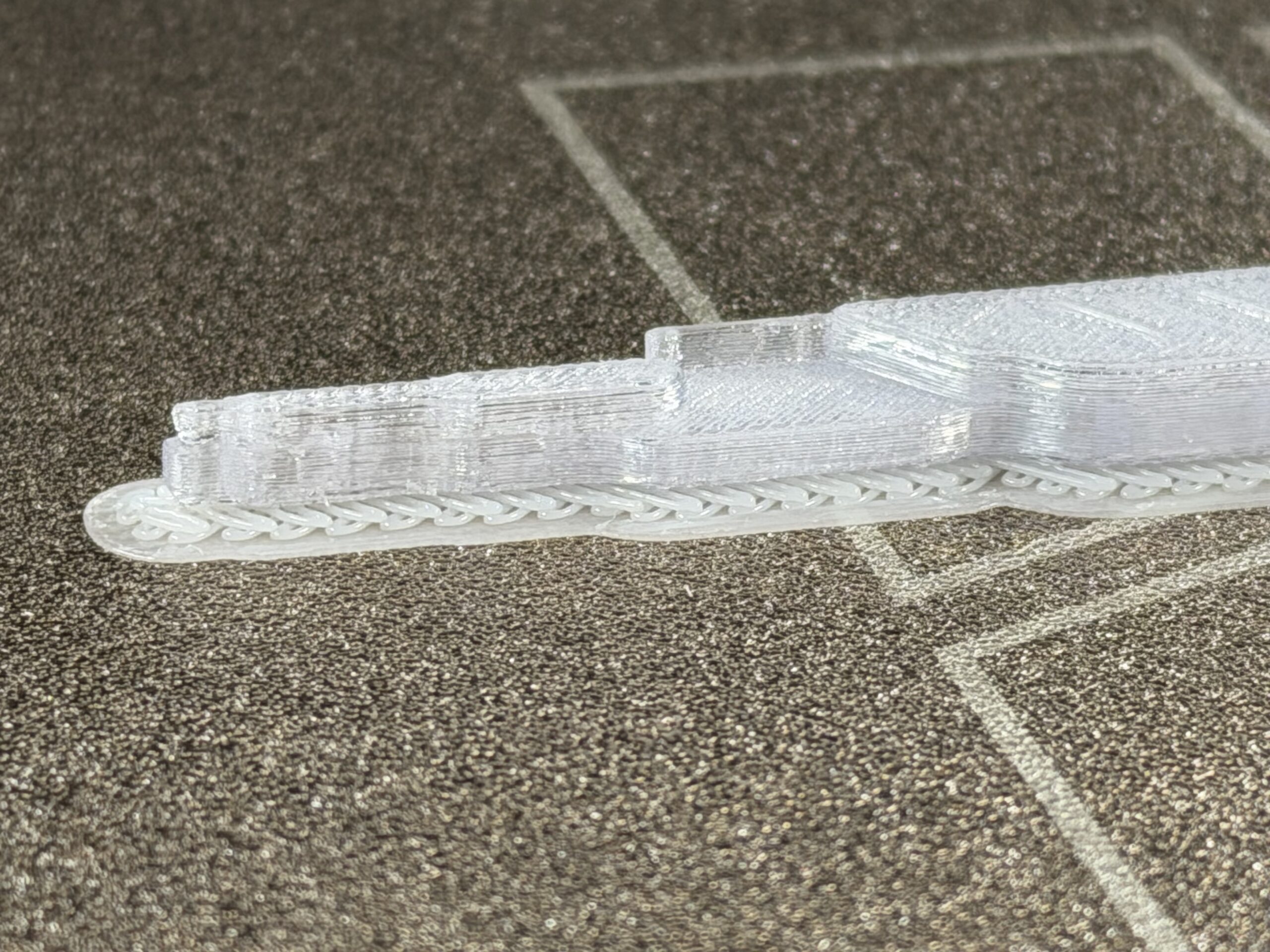
- the ABS raft is deposited first
- the first layer of PC is extruded at high temperature
- a strong inter-layer bond forms between the two materials
ABS interface
The raft acts as a controlled technical interface between the build plate and the PC part.
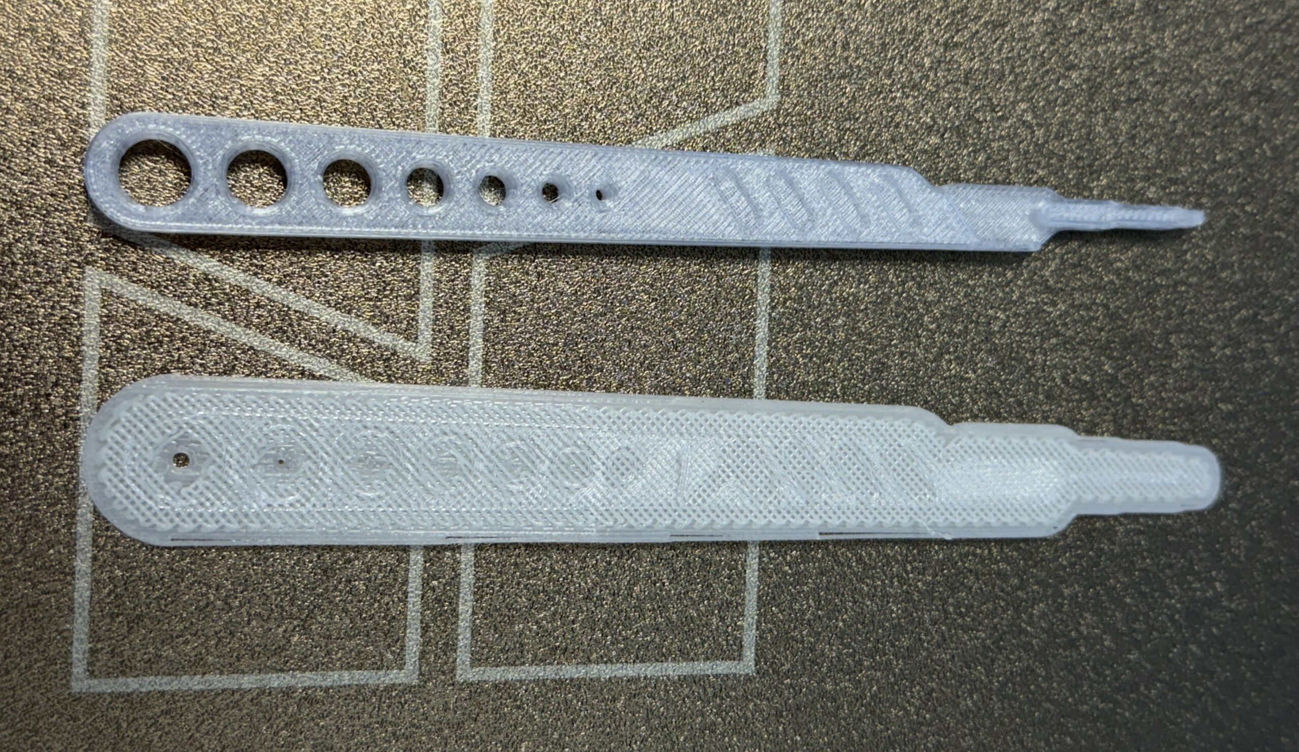
The raft provides:
- better grip on the build plate
- reduced warping
- clean separation after printing
Advantages of the ABS Raft Over Adhesives
Preserved Biocompatibility
By using a qualified ABS grade such as ISO 10993-5 (Lattice Services ABS), no external glue, solvent, or additive is required. This keeps the print environment clean and suitable for medical or sensitive applications.
Elimination of Chemical Consumables
Build plate cleaning and removal of adhesive residue are greatly reduced, or eliminated altogether. At the end of the cycle, the PC part detaches mechanically, the build plate stays clean, and the process is more repeatable.
Lower Production Costs
In an industrial context, a raft for a small part typically uses 1 to 5 g of ABS material. Compared to specialized adhesion consumables, this approach lowers cost per cycle, standardizes processes, and limits losses from failed prints.
Improved Print Stability
The ABS raft provides a stable base even on standard build plates (PEI, glass, etc.), limiting deformation from the very first layers.
Adhesives vs ABS Raft
| Criterion | Adhesives / PC glues | ABS Raft |
|---|---|---|
| Part retention | Adhesives / PC gluesVariable | ABS RaftHigh and stable |
| Post-print cleanliness | Adhesives / PC gluesFrequent residue | ABS RaftClean |
| Biocompatibility | Adhesives / PC gluesCompromised if adhesive is not ISO 10993-5 | ABS RaftPreserved |
| Cost per cycle | Adhesives / PC gluesHigh | ABS RaftLow |
| Repeatability | Adhesives / PC gluesModerate | ABS RaftHigh |
Recommended Slicer Settings
To implement this method, the following settings provide a good starting point. The parameters below correspond to Lattice Services material profiles for the Bambu Lab H2D with a 0.4 mm nozzle using BambuStudio. Adjustments may be needed depending on part geometry, print surface, and usage conditions.
General Configuration
Settings differ slightly depending on whether your printer has two nozzles (one per material) or a single nozzle (filament change mid-print).
| Criterion | 2-Nozzle Setup | 1-Nozzle Setup |
|---|---|---|
| Extruders | 2-Nozzle SetupExtruder 1: ABS Medical (raft) Extruder 2: PC Medical (part) | 1-Nozzle SetupExtruder 1: ABS Medical (raft) |
| Raft enabled | 2-Nozzle SetupMandatory | 1-Nozzle SetupMandatory |
| Number of raft layers | 2-Nozzle Setup3 layers min. | 1-Nozzle Setup3 layers min. |
| Raft-to-object Z distance | 2-Nozzle Setup0.09 – 0.11 mm | 1-Nozzle Setup0.09 – 0.11 mm |
| If your slicer allows you to select a different filament for the part and the raft, select ABS for the raft and PC for the part. | ||
| If your slicer does not allow you to select a filament for the raft that differs from the part, slice your part with ABS and then perform a filament change via G-code to PC at the layer following your raft. This will prevent the supports from printing in ABS. | ||
If you experience adhesion difficulties with these settings, increase the raft width using the “first layer expansion” option.
Recommended Temperatures
Nozzle and build plate temperatures are set based on the material and the selected print surface.
| Parameters | ABS Medical | PC Medical |
|---|---|---|
| Nozzle temperature – 1st layer | 260 °C | 270 °C |
| Nozzle temperature – other layers | 250 – 255 °C | 270 – 280 °C |
| Engineering Plate | 90 – 100 °C | 110 – 120 °C |
| Smooth PEI / High Temp Plate | 90 – 100 °C | 110 – 120 °C |
| Textured PEI Plate | 100 °C | 120 °C |
| Chamber temperature | Maximum | Maximum |
Optimization Tips
- Avoid drafts (an enclosed chamber is recommended)
- Precisely calibrate the first ABS layer
- Adjust the interface height to maximize PC/ABS adhesion
- If needed, you can widen the raft using the “First Layer Expansion” option to 10mm, then increase it gradually
Two material configurations for Ultimaker and BambuLab are available in the resources tab. You can also refer to our technical data sheets and product pages.